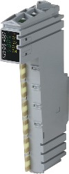
Short description
| I/O module | IO-Link master with 4 IO-Link interfaces |
General information
| B&R ID code | 0xA38E |
| Status indicators | IO-Link, operating state, module status |
| Diagnostics | |
| Module run/error | Yes, using LED status indicator and software |
| IO-Link operating state | Yes, using LED status indicator and software |
| C/Q status | Yes, using LED status indicator and software |
| Cable specification | |
| Cable type | 3-pin standard sensor cable |
| Cable length | Max. 20 m |
| Line capacitance | Max. 3 nF |
| Loop resistance | Max. 6 Ω |
| Power consumption | |
| Bus | 0.01 W |
| Internal I/O | 1.6 W |
| Additional power dissipation caused by actuators (resistive) [W] | - |
| Certifications | |
| CE | Yes |
| UKCA | Yes |
| ATEX |
Zone 2, II 3G Ex nA nC IIA T5 Gc IP20, Ta (see X20 user's manual) FTZÚ 09 ATEX 0083X |
| UL |
cULus E115267 Industrial control equipment |
| HazLoc |
cCSAus 244665 Process control equipment for hazardous locations Class I, Division 2, Groups ABCD, T5 |
| KC | Yes |
Sensor/Actuator power supply
| Voltage | I/O power supply minus voltage drop for short-circuit protection |
| Voltage drop for short-circuit protection at 0.3 A | Max. 1 VDC |
| Power consumption | Max. 9 W per interface |
| Short-circuit proof | Yes |
IO-Link in master mode
| Transfer rates | |
| COM1 | 4.8 kbaud |
| COM2 | 38.4 kbaud |
| COM3 | 230.4 kbaud |
| Limit values for COM3 | |
| Max. connection capacity | 47 nF (cable and device) |
| Max. load | 100 Ω / 0.3 A |
| Data format | 1 start bit, 8 data bits, 1 parity bit (even), 1 stop bit |
| Bus level | 24 VDC (active), 0 VDC (resting voltage) |
| IO-Link device power supply | 24 VDC / Max. 0.3 A per interface (fused) |
IO-Link in master mode or in SIO mode "digital output"
| Variant | Bipolar, positive and negative switching |
| Diagnostics | Output monitoring with 100 ns delay and internal protection of the semiconductor with 100 µs delay |
| Peak short-circuit current | <1.5 A |
| Residual voltage | <1.5 VDC at nominal current 0.2 A |
| Switching voltage | I/O power supply minus voltage drop for short-circuit protection and semiconductor switch |
| Voltage drop on semiconductor switch | Max. 1.5 VDC at 0.2 A |
| Switching frequency |
Typ. 25 kHz 300 kHz in IO-Link master mode |
| Switching delay | |
| 0 → 1 | <10 µs |
| 1 → 0 | <10 µs |
| Switch-on in the event of overload shutdown or short-circuit shutdown | Approx. 10 ms (depends on the module temperature) |
| Braking voltage when switching off inductive loads | Typ. 52 VDC |
| Insulation voltage between IO-Link and bus | 500 Veff |
IO-Link in SIO mode "Digital output"
| Nominal voltage | 24 VDC |
| Nominal output current | 0.2 A |
| Total nominal current | 0.4 A |
| Output circuit | Sink or source |
| Output protection | Thermal shutdown in the event of overcurrent or short circuit, integrated protection for switching inductive loads |
| Actuator power supply | 24 VDC / Max. 0.3 A per interface (fused) |
IO-Link in SIO mode "digital input"
| Nominal voltage | 24 VDC |
| Input filter | |
| Hardware | 100 ns |
| Software | - |
| Input circuit | Sink |
| Sensor power supply | 24 VDC / Max. 0.3 A per interface (fused) |
| Input voltage | 24 VDC -15% / +20% |
| Input current at 24 VDC | Typ. 5 mA |
| Input resistance | Typ. 4.8 kΩ |
| Switching threshold | |
| Low | <8 VDC |
| High | >13 VDC |
| Insulation voltage between IO-Link and bus | 500 Veff |
Electrical properties
| Electrical isolation |
Bus isolated from IO-Link IO-Link not isolated from IO-Link
|
Operating conditions
| Mounting orientation | |
| Horizontal | Yes |
| Vertical | Yes |
| Installation elevation above sea level | |
| 0 to 2000 m | No limitation |
| >2000 m | Reduction of ambient temperature by 0.5°C per 100 m |
| Degree of protection per EN 60529 | IP20 |
Ambient conditions
| Temperature | |
| Operation | |
| Horizontal mounting orientation | 0 to 55°C |
| Vertical mounting orientation | 0 to 45°C |
| Derating | - |
| Storage | -25 to 70°C |
| Transport | -25 to 70°C |
| Relative humidity | |
| Operation | 5 to 95%, non-condensing |
| Storage | 5 to 95%, non-condensing |
| Transport | 5 to 95%, non-condensing |
Mechanical properties
| Note |
Order 1x terminal block X20TB12 separately. Order 1x bus module X20BM11 separately. |
| Pitch | 12.5+0.2 mm |

Materialnummer:
X20DS4387Beskrivning:
- 4 IO-Link interfaces per module
- Each interface can be configured as a standard input or output
- Seamless integration in POWERLINK
- Supports all transfer rates
IO-Link is a standardized communication system for connecting intelligent sensors and actuators in an automation system. The standardization includes electrical connection data as well as a digital communication protocol, which is used by the sensors and actuators in the automation system for data exchange.
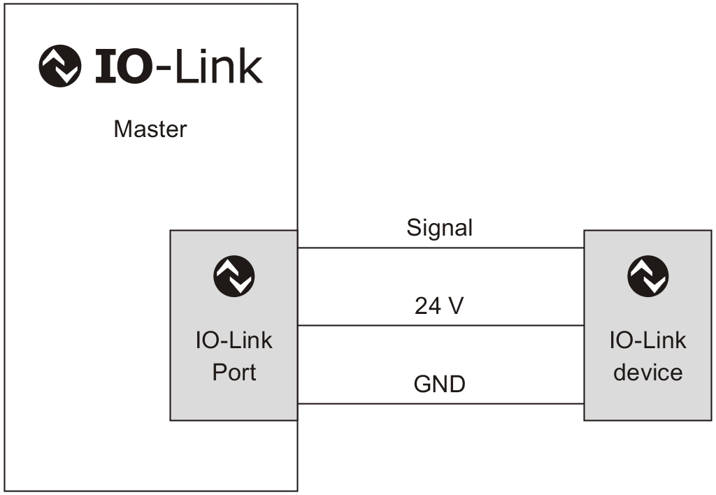
An IO-Link system consists of an IO-Link master and one or more IO-Link devices, i.e. sensors and actuators. The IO-Link master makes the interface available for higher level control and controls communication with the connected IO-Link devices.
An IO-Link device is an intelligent sensor or actuator. With regard to IO-Link, "intelligent" means that a device possesses a series number or parameter data (sensitivity, switching delays or characteristic curves), which can be written to or read via the IO-Link protocol.

Process optimization
The use of intelligent sensors and actuators contributes to process optimization. Process optimization means that downtimes should be kept as short as possible. These consist mainly of standstills due to errors and setup times.
Integrated communication down to the IO-Link devices offers many advantages in error diagnostics. Errors are detected much faster than before. If a sensor or actuator must be replaced, lengthy configuration work is no longer necessary after the change thanks to a potentiometer, or a configuration tool and laptop. After changing the sensor/actuator, the parameters are automatically transferred to the sensor.
This parameter download is not only beneficial when errors occur. It can also be used for changing parameters when a load change is performed. This shortens setup times, making product changes and small batches more economical.
Integrating IO-Link into the X20 System
IO-Link is integrated in the X20 system using this digital module. All 4 channels are IO-Link interfaces, but can also be used as standard inputs or outputs. The specified 3-wire connections can be ideally implemented thanks to the X20 connector system with 12 terminal points per module. All specified transfer rates are also supported.
POWERLINK integration
IO-Link doesn't stop at the I/O module. It must be integrated in the higher-level bus system to fully utilize the benefits. When using POWERLINK, access is made possible via device description files in XML format.
Obligatoriska tillbehör
| Automation Studio HW uppdateringar | Version (datum) | Ladda ner |
|---|---|---|
| V2.7 HW Upgrade (X20DS4387) | EXE / 1 MB | |
| V3.0 HW Upgrade (X20DS4387) | EXE / 1 MB | |
| V4.0 HW Upgrade (X20DS4387) | EXE / 775 KB |
| Certifikat | Version (datum) | Ladda ner |
|---|---|---|
| 244665 CSA HazLoc CoC X20, X67 | PDF / 158 KB | |
| E115267 UL CoC X20 | PDF / 1 MB | |
| FTZU 09 ATEX 0083X | PDF / 771 KB | |
| X20, X67 KC certificates | PDF / 6 MB |
| Dokumentation | Version (datum) | Ladda ner |
|---|---|---|
| Data sheet X20DS4387 | PDF / 466 KB | |
| Installation- / EMC-Guide | PDF / 20 MB | |
| X20 Package leaflet ATEX/CSA | PDF / 2 MB | |
| X20 System User´s Manual | PDF / 7 MB |
| E-CAD (Electro eller EPLAN mallar) | Version (datum) | Ladda ner |
|---|---|---|
| X20 EPLAN P8 from V2.4 | EXE / 160 MB |
| M-CAD (Mechan. mallar) | Version (datum) | Ladda ner |
|---|---|---|
| 3D File DXF/STEP X20 Electronic module | ZIP / 10 KB | |
| 3D File STEP X20 I/O-Slice | ZIP / 872 KB | |
| Dimensions PDF X20 Electronic module | PDF / 3 KB |