Overview of motor-gearbox combinations and gear ratios
Overview of motor-gearbox combinations and gear ratios
8GM40 | 8GM50 | |||||
|---|---|---|---|---|---|---|
Gearbox size | 40 | 60 | 80 | 50 | 70 | 90 |
Motor | ||||||
8LVB13 n = 1500 rpm | Yes | - | - | Yes | - | - |
8LVB13 n = 1500 rpm with brake | Yes | - | - | Yes | - | - |
8LVB13 n = 3000 rpm | Yes | - | - | Yes | - | - |
8LVB13 n = 3000 rpm with brake | Yes | - | - | Yes | - | - |
8LVB22 n = 1500 rpm | - | Yes | - | - | Yes | - |
8LVB22 n = 1500 rpm with brake | - | Yes | - | - | Yes | - |
8LVB22 n = 3000 rpm | - | Yes | - | - | Yes | - |
8LVB22 n = 3000 rpm with brake | - | Yes | - | - | Yes | - |
8LVB23 n = 1500 rpm | - | Yes | - | - | Yes | - |
8LVB23 n = 1500 rpm with brake | - | Yes | - | - | Yes | - |
8LVB23 n = 3000 rpm | - | Yes | - | - | Yes | - |
8LVB23 n = 3000 rpm with brake | - | Yes | - | - | Yes | - |
8LVB33 n = 1500 rpm | - | - | Yes | - | - | Yes |
8LVB33 n = 1500 rpm with brake | - | - | Yes | - | - | Yes |
8LVB33 n = 2100 rpm | - | - | Yes | - | - | Yes |
8LVB33 n = 2100 rpm with brake | - | - | Yes | - | - | Yes |
Available ratios (iii)
Planetary gearboxes for direct motor mounting – Order code (iii) | ||
|---|---|---|
Gearbox series | 1-stage | 2-stage |
8GM40 | 003, 004, 005, 008, 010 | 009, 012, 015, 016, 020, 025, 032, 040, 064, 100 |
8GM50 | 003, 004, 005, 008, 010 | 009, 012, 015, 016, 020, 025, 032, 040, 064, 100 |
Cooling / Construction type
Cooling / Construction type
The 8LVB motor/gearbox combinations are self-cooling and extremely compact due to motor/gearbox direct mounting.
Valid code: B
Size (c)
Size (c)
The 8LVB motor/gearbox combination is available in three different sizes (1, 2, 3). They have different dimensions and power data. These different sizes are indicated by a number represented by (c) in the model number. The larger the number, the larger the flange dimensions and power data for the respective motor.
Cooling / Construction type | Available sizes | ||
|---|---|---|---|
1 | 2 | 3 | |
B | Yes | Yes | Yes |
Valid codes: 13, 22, 23, 33
Length (d)
Length (d)
The motor integrated in the 8LVB motor/gearbox combination is available in 2 different lengths. They have different power data with identical flange dimensions. The various lengths are differentiated by a number (d) in the order key.
Length | Available sizes | ||
|---|---|---|---|
1 | 2 | 3 | |
2 | --- | Yes | --- |
3 | Yes | Yes | Yes |
Valid codes: 13, 22, 23, 33
Encoder system (ee)
Encoder system (ee)
Encoders are listed as part of the model number in the form of a 2-digit code (ee).
Size/Length | Code for order key (ee) / Availability of motor encoders | |||
|---|---|---|---|---|
R0 | B1 | B8 | B9 | |
8LVx13 | Yes | Yes | --- | --- |
8LVx22 | Yes | Yes | Yes | Yes |
8LVx23 | Yes | Yes | Yes | Yes |
8LVx33 | Yes | Yes | Yes | Yes |
General
Motors in the 8LV series are available with EnDat encoders as well as resolvers. The encoder system is listed as part of the model number in the form of a 2-digit code (ee).
A resolver is an analog encoder system. Resolvers are particularly robust against vibrations and high operating temperatures. A disadvantage is the low accuracy of 6-10 arcmin. Furthermore, no multi-turn variant with resolvers is possible.
Digital encoders use a serial transfer protocol. This protocol is called EnDat. The EnDat protocol is a developed standard that incorporates the advantages of absolute and incremental position measurement and also offers a read/write parameter memory in the encoder. The embedded parameter chip is stored by B&R in this encoder memory. This data and the B&R ACOPOS systems form a plug-and-play drive solution. Absolute positioning can be used within a revolution with the single-turn variants. A homing procedure is not required because of the absolute position measurement. For applications where the motor covers several revolutions for positioning, a multi-turn encoder that can save up to 65535 revolutions can be used. A solution with a single-turn encoder variant with a homing procedure is also possible.
Resolver
RE-15-1-J04 resolvers are used in the motors.
Encoder type / Order code (ee) | |
|---|---|
R0 | |
Precision | 10 angular minutes |
Vibration during operation | ≤500 m/s² |
Shock during operation | ≤1,000 m/s² |
EnDat 2.2 encoder
For the advanced, fully digital EnDat 2.2 protocol, the positions are generated directly in the encoder and communicated serially with the drive system. This transfer is very robust in relation to disturbances and is even certified for safety applications.
Digital drive systems and position control loops require fast and highly secure transfer of data obtained from position measuring instruments. In addition, other data such as drive-specific characteristics, correction tables, etc. should also be available. To ensure a high level of system security, measuring instruments must be integrated in routines for detecting errors and be able to perform diagnostics.
The EnDat interface from HEIDENHAIN is a digital, bidirectional interface for measuring instruments. It is able to output position values from incremental and absolute measuring instruments and can also read and update information on the measuring instrument or store new data there. Because it relies on serial data transfer, only 4 signal lines are needed. Data is transferred synchronously to the clock signal defined by the subsequent electronics. The type of transfer used (e.g. for position values, parameters, diagnostics, etc.) is selected using mode commands sent to the measuring instrument by the subsequent electronics.
Encoder type / Order code (ee) | |||
|---|---|---|---|
B1 | B8 | B9 | |
Operating principle | Inductive | ||
EnDat protocol | EnDat 2.2 | ||
Single-turn / Multi-turn | M | S | M |
Battery-backed | Yes | --- | |
Revolutions | 65536 | 1 | 4096 |
Resolution [bits single-turn / bits multi-turn] | 18/16 | 19/0 | 19/12 |
Precision [''] | 120 | ||
Switching frequency ≥ [kHz] | Digital pos. in the encoder | ||
Vibration during operation - Stator Max [m/s2] | 300 | 400 | |
Vibration during operation - Rotor Max [m/s2] | 300 | 600 | |
Max. shock during operation [m/s2] | 1000 | 2000 | |
Manufacturer's product ID | EBI 1135 | ECI 1119 FS | EQI 1131 FS |
Manufacturer's website | www.heidenhain.de | ||
Valid codes: R0, B1, B8, B9
Available ratios (iii)
Available ratios (iii)
Planetary gearboxes for direct motor mounting – Order code (iii) | ||
|---|---|---|
Gearbox series | 1-stage | 2-stage |
8GM40 | 003, 004, 005, 008, 010 | 009, 012, 015, 016, 020, 025, 032, 040, 064, 100 |
8GM50 | 003, 004, 005, 008, 010 | 009, 012, 015, 016, 020, 025, 032, 040, 064, 100 |
Valid codes: 003, 004...100, see table
Output shaft (jj)
Output shaft (jj)
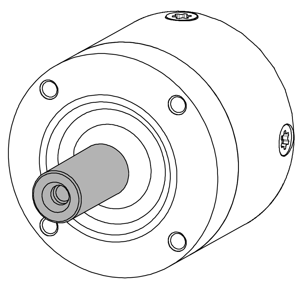
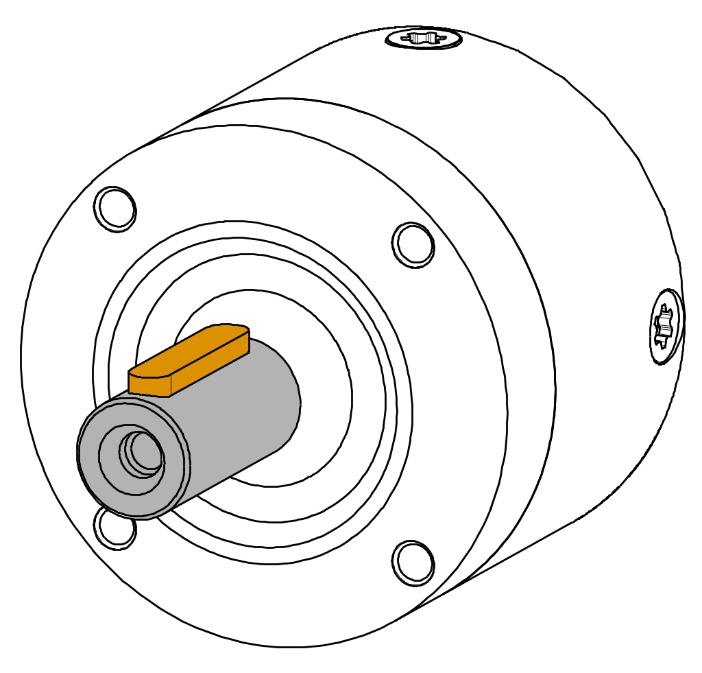
The motor/gearbox combinations from the 8LVB series can be delivered with a smooth or keyed shaft end.
| Smooth shaft endA smooth shaft end is used for a force-fit shaft-hub connection and guarantees a backlash-free connection between the shaft and hub as well as a high degree of operating smoothness. The end of the shaft has a threaded center hole. |  |
| Keyed shaft endA keyed shaft end is used for a form-fit torque transfer with low demands on the shaft-hub connection and for handling torque in a constant direction. The keyways of the gear units of the 8LVB series conform to keyway form N1 in accordance with DIN 6885-1. The end of the shaft has a threaded center hole that can be used to mount machine actuators with shaft end cover plates. |  |
Valid codes: see table "Determining the order code for device options"
Holding brake (jj)
Holding brake (jj)
Motors in the 8LV series can be delivered with a holding brake. It is used to hold the motor shaft when no power is applied to the motor.
Motor size | |||
|---|---|---|---|
1 | 2 | 3 | |
Holding torque MBr [Nm] | 0.35 | 2.2 | 3.2 |
Connected load POn [W] | 8 | 8.4 | 13.4 |
Maximum speed nmax [rpm] | 6000 | 12000 | 12000 |
Supply current IOn [A] | 0.33 | 0.35 | 0.56 |
Supply voltage UOn [V] | 24 VDC +6% / -10% | 24 VDC +6% / -10% | 24 VDC +6% / -10% |
Moment of inertia JBr [kgcm²] | 0.013 | 0.07 | 0.38 |
Mass mBr [kg] | 0.1 | 0.16 | 0.29 |
Valid codes: see table "Determining the order code for device options"
Determining the order code for device options (jj)
Determining the order code for device options (jj)
The code(jj) with the corresponding device options can be found in the following table:
Gearbox series 8GM40 | Motor option Holding brake | Output Shaft end | Code for order key (jj) |
|---|---|---|---|
--- | Smooth | S0 | |
--- | With key | S1 | |
Yes | Smooth | S4 | |
Yes | With key | S5 |
Gearbox series 8GM50 | Motor option Holding brake | Output Shaft end | Code for order key (jj) |
|---|---|---|---|
--- | Smooth | L0 | |
--- | With key | L1 | |
Yes | Smooth | L4 | |
Yes | With key | L5 |
Nominal speed / Connection type (nn)
Nominal speed / Connection type (nn)
The first position (nn) of the two-position code (nn) is the nominal speed. The second position (nn) is the connection type.
The nominal speed (nn) of the motor is specified as the speed class in the order key. Speed class is broken up into steps of 500 [rpm] and begins at 80 VDC operation at A = 500 [rpm]. (Deviations include nominal speed 950 [rpm] as class B = 1000 [rpm] and nominal speed 2100 [rpm] as class D = 2000 [rpm].)
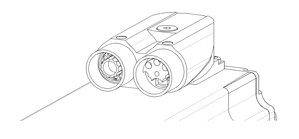
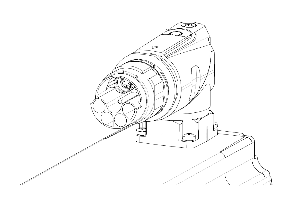
The connection type (nn) of the motor in represented in the order key with nW for double angular built-in connector and nS for single-cable solution (hybrid).
 Double angular built-in connector (nW) |  Single-cable solution (nS) |
Available combinations
Size/Length | Available nominal speeds nN [rpm] at 80 VDC operation | ||
|---|---|---|---|
1500 | 2100 | 3000 | |
Code for nominal speed class (nn) (code for nominal speed class and connection type) | |||
Cn (CW/CS) | Dn (DW/DS) | Fn (FW/FS) | |
8LVB131) | Yes | --- | Yes |
8LVB22 | Yes | --- | Yes |
8LVB23 | Yes | --- | Yes |
8LVB33 | Yes | Yes | --- |
| 1) | Not all motor encoders are available for this size. See the motor encoder availability table. |
Example: The 2-position code (nn) for nominal speed 1500 nN [rpm] is either CW or CS for the double angular built-in connector or single-cable solution (hybrid), respectively.
Special options (ll)
Special options (ll)
No special options are currently offered for 8LVB gear motors. Valid code: 00
Example order 1
Example order 1
A servo gear motor of type 8LVB 13 with a rated speed of 1500 rpm was selected for an application. The motor should be equipped with a holding brake and an EnDat encoder (B1). The gearbox should have a gear ratio of i = 010 and the shaft end should have a key. The connection type should be a double angular built-in connector.
The code for the encoder system (ee) is B1.
The code for the gear ratio (iii) is 010.
The code for standard gearboxes with a keyed output shaft is S5.
The code for the motor brake here is 5 (already included in S5!).
The code for nominal speed (nn) 1500 rpm is C.
The code for the double angular built-in connector connection type (nn) is W.
The model number for the required motor/gearbox combination is 8LVB13.B1010S5CW00.
Example order 2
Example order 2
A servo gear motor of type 8LVB 33 with a nominal speed of 2100 rpm was selected for an application. The motor should not be equipped with a holding brake. It should be equipped with EnDat encoder B8. The gearbox should have a gear ratio of i = 020 and a smooth shaft end. Gearbox 8GM50 was selected. The connection type should be a single-cable solution (hybrid).
The code for the encoder system (ee) is B8.
The code for the gear ratio (iii) is 020.
The code for gearbox 8GM50 with a smooth output shaft is L0.
The code for the option without a motor brake is 0 here (already included in L0!).
The code for the nominal speed (nn) 2100 rpm is D (2100 rpm is assigned to speed class D = 2000 rpm).
The code for the angled single-cable solution (hybrid) connection type (nn) is S.
The model number for the required motor/gearbox combination is 8LVB33.R0020L0DS00.